The compressed air distribution system has the task of distributing the energy carrier compressed air with the least possible influence on the air quality.
- of the air quality (due to rust, water, welding scale, etc.),
- the flow pressure (due to uneconomical pressure losses) and
- quantity (due to unnecessarily high leakages).
transport.
Pressure drops are costly
Each compressed air consumer in the network requires a specific, optimum operating pressure. Too low an operating pressure, caused for example by too narrow pipe cross-sections, disproportionately reduces the consumer's performance.
Excessively high pressures, on the other hand, not only drive up energy costs unnecessarily, but also shorten the service life of the consumers.
Piping dimensioning
Of course, the correct dimensioning of the compressed air network also has a direct influence on the performance of the compressors, the consumers and thus the costs of compressed air production.
The most important design criteria for the compressed air network are:
- the volume flow
- the operating pressure
- the line length
- the pressure drop
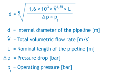
Taking these criteria into account, the correct diameter of the compressed air line can be determined. The dimensioning of the pipeline diameter is done either
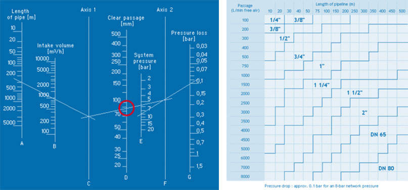
- by using common design diagrams/nomograms,
- by means of common tables from which the diameters can be read off directly, or
- mathematically by means of an approximation formula:
First, line A (pipe length) is connected to line B (suction volume) and extended to axis 1. Then line E (system pressure) is connected to line G (target pressure drop). Finally, the resulting intersections on axes 1 and 2 are connected by a straight line. This straight line intersects line D; the required clear pipe width can then be read from this line.
In general, the nominal size of the compressed air line should be as large as possible. The greatest pressure losses are caused by compressed air lines that are too small or too tightly dimensioned.
Experience shows that in the case of an originally correctly dimensioned compressed air network, more and more consumers have been added to the existing line network over the course of time without the network being re-dimensioned to meet the new requirements.
It is not uncommon for only the compressor capacity to be increased to cover the increased consumption.
Economically justifiable pressure drop
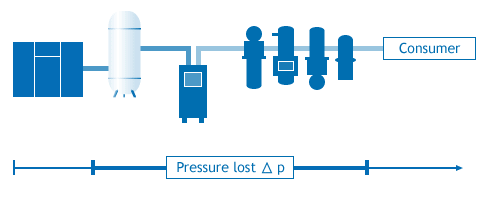
The pressure drop, from generation to consumer, in an optimally designed compressed air network is subdivided as follows:
- < 0.03 bar for the main line (line between compressor room/tank and main consumption center).
- < 0.03 bar for the ring/distribution line (line section that distributes the air within a consumption center)
- < 0.04 bar for the connection line/spur line (connection between the distribution line and the consumer).
The pressure loss in the individual components of the compressed air preparation can be represented as follows:
The amount of the total pressure drop depends on:
- Degree of contamination and number of treatment components.
- Type and number of fittings
- Nominal size of the compressed air piping system
The more unfavorably a compressed air line is designed, the more a compressor must perform to build up and maintain the required pressure. This means: 1 bar loss in the compressed air system = 1 bar more power at the compressor = approx. 10% higher power consumption.
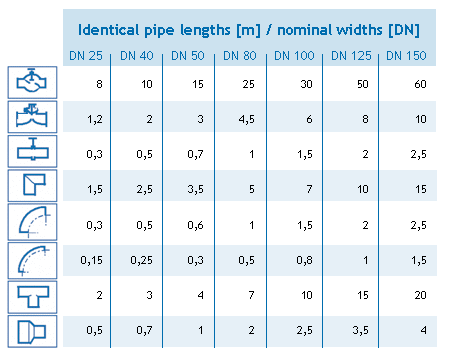
Influence of piping elements
Every element in a compressed air piping system, be it a treatment component or fittings of the piping, cause a pressure loss due to flow resistance.
Considering the pressure losses due to fittings, a straight pipeline would be ideal in this context. However, due to structural conditions, pipelines cannot usually be laid from the producer to the consumer without fittings.
Deflections, such as when bypassing support pillars, can be avoided by laying the compressed air line next to the obstacle.
90° elbows can easily be replaced by large dimensioned 90° elbows (see Fig. 5). This can reduce the pressure loss to a fraction of the original pressure loss.
In addition to these influences, materials adapted to the different applications must also be used. The use of the correct materials depends on the following influencing factors:
- Compressed air quality,
- dimensions of the tubes,
- pressure,
- environmental influences,
- installation effort and
- material costs.


